
Copper-clad steel grounding system solutions by project type
The same CCS conductor does very different jobs in a PV array and in a 220 kV substation: the first is tens of kilometres of equipotential bonding with small fault currents and a theft problem; the second is a few kilometres of main grid with large fault currents and a heat problem. This page gives typical duty, recommended copper thickness and sizes by project type as a starting point for early design. The final selection is the sizing report calculated from your actual fault current, soil and design life – which we provide free within 24–48 hours.
"System" here means the complete set of materials and selection services a grid needs: horizontal conductor, vertical rods, leads and exothermic welding, with IEEE 80 section and copper-thickness sizing, test documentation and site guidance. Grid resistance and touch and step voltages depend on grid geometry and soil; we calculate them to IEEE Std 80-2013 / GB/T 50065-2011 and issue the report for the design institute to review.
Earth resistance depends only on the shape and area of the electrode and the soil resistivity, not on the material; the material decides the service life.
So we do two things: get the earth resistance, step voltage and touch voltage right to IEEE Std 80-2013 / GB/T 50065-2011, and get the service life right with thick-layer continuous-cast copper-clad steel. Our chief engineer is the author of Grounding Design and Engineering Practice (China Machine Press, 2014) and signs every scheme.
By design step
Survey and layering
Four-pin method, apparent-resistivity inversion, the reflection-criterion criterion; four failures from drilling deep without measuring deep.
The right order for lowering resistance
One dimension beats two beats three; extend → lead out → long rods → deep wells; shape efficiency decides everything.
Step and touch voltage
IEEE 80 tolerable values, mesh voltage, what the crushed-rock layer does; with a grid-resistance and tolerable-voltage calculator.
Tower radial design table
Radial length and calculated resistance by soil resistivity; with a radial-electrode calculator.
By project type
All eight sector pages are written as a design walk-through – targets, then layout, then material, with calculators; we issue the calculation to IEEE 80 / GB/T 50065 for the design institute to check.
Three basic forms, combined into every industry
Power earthing has only three basic forms; every other sector is a combination of them. Get the three right first, then stack them by industry.
Industry solutions
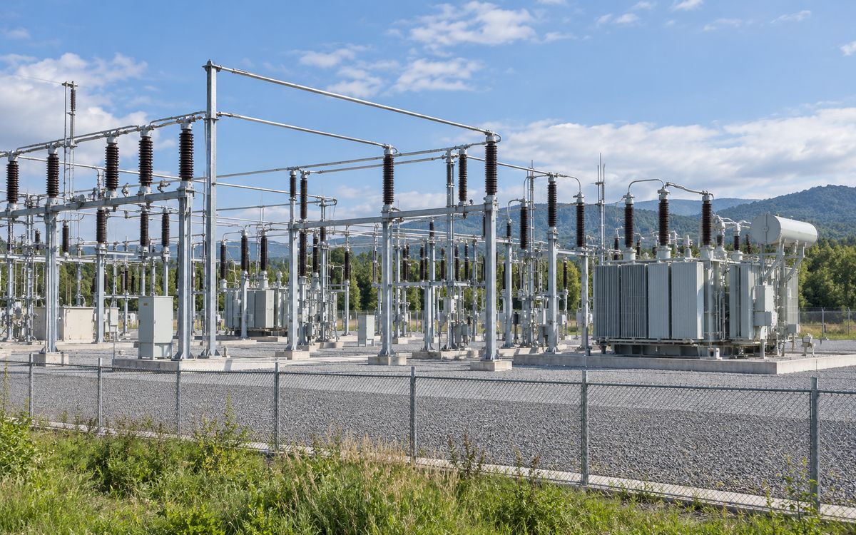
Substations
Combination: basic form ①
Replaceable at 110 / 220 kV; at 330 kV and above we say so.
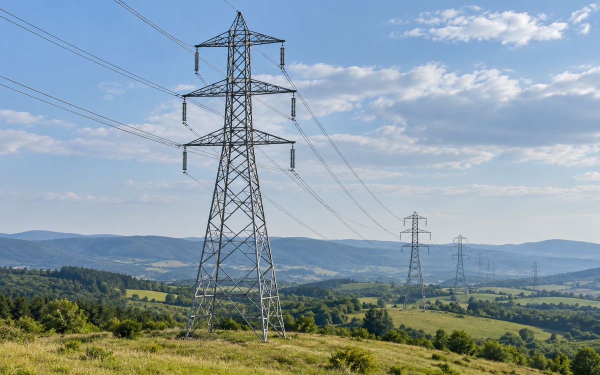
Transmission-line towers
Combination: basic form ②
Radials and rods; soil varies along the route; theft drives the switch.
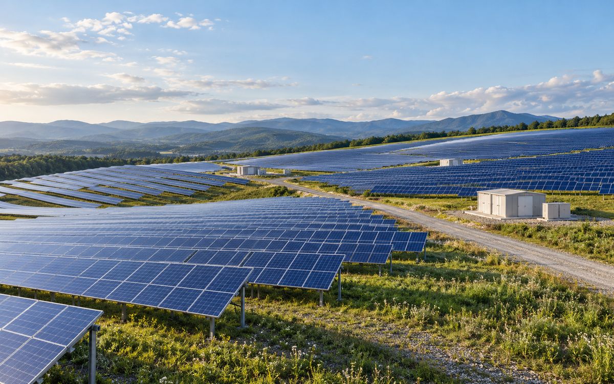
PV plants
Combination: array field mesh-plus-ring, plus a step-up substation ①①
The biggest segment by kilometres laid; soil and theft are the real enemies.
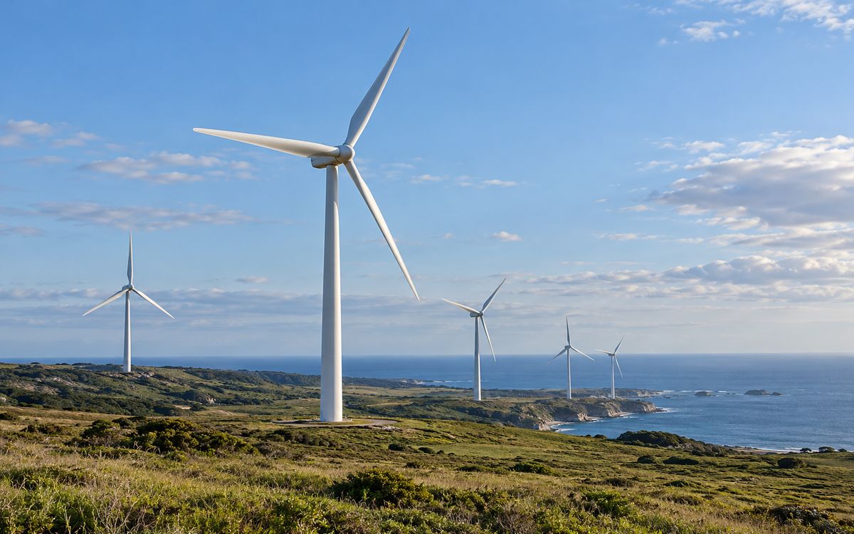
Wind farms
Combination: collector substation ① + twenty or thirty turbine foundations ②
High lightning current and coastal salt; ring electrode plus radials.
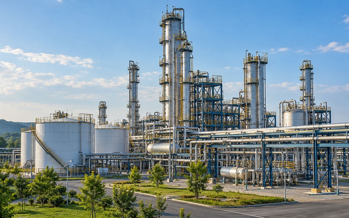
Chemical / coal-chemical / oil & gas
Combination: intake substation ① + building rings ③ + CP coordination
High fault current plus acid, alkali and salt soil: the textbook case.
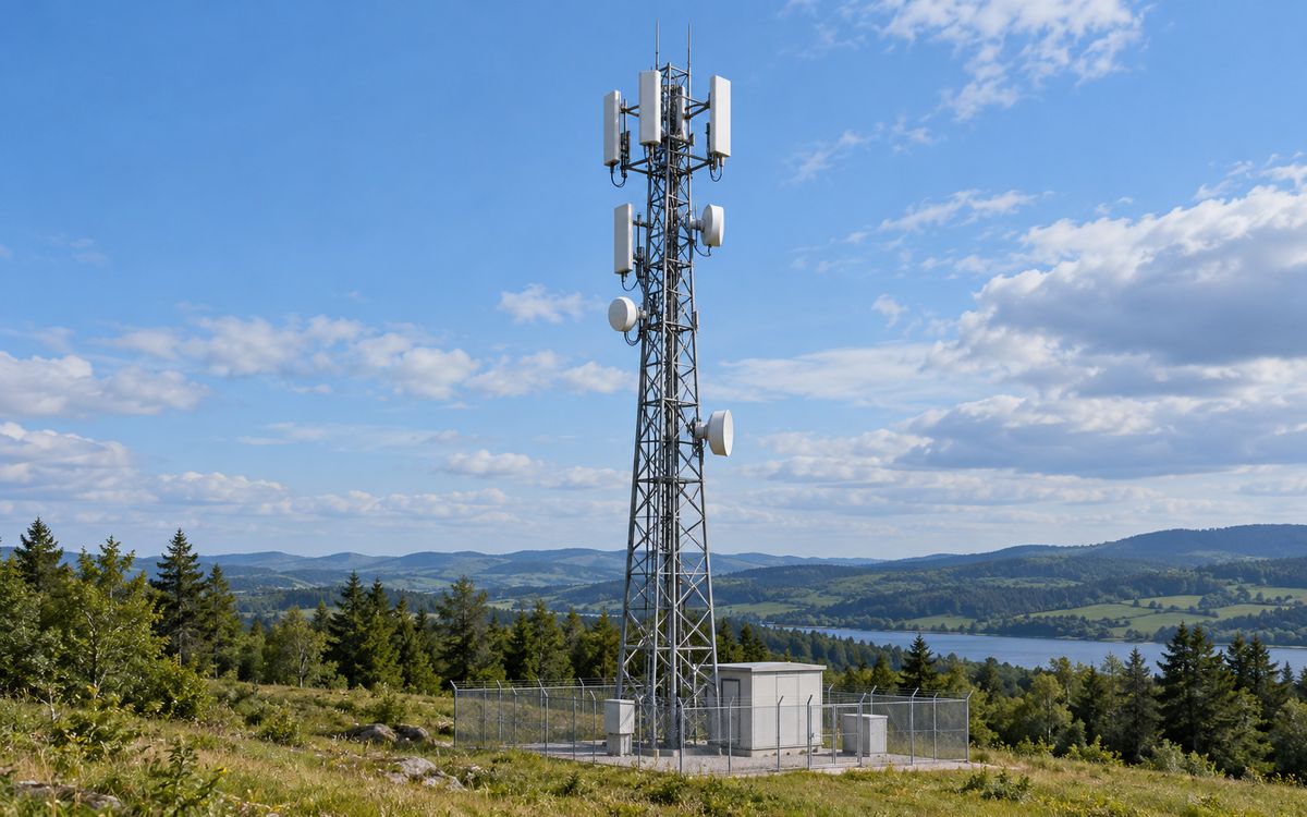
Telecom towers / base stations
Combination: remote hilltop = tower ②; crowded indoor site = ring + grading ③
Lightning-driven, small per site; where plated rods fit best.
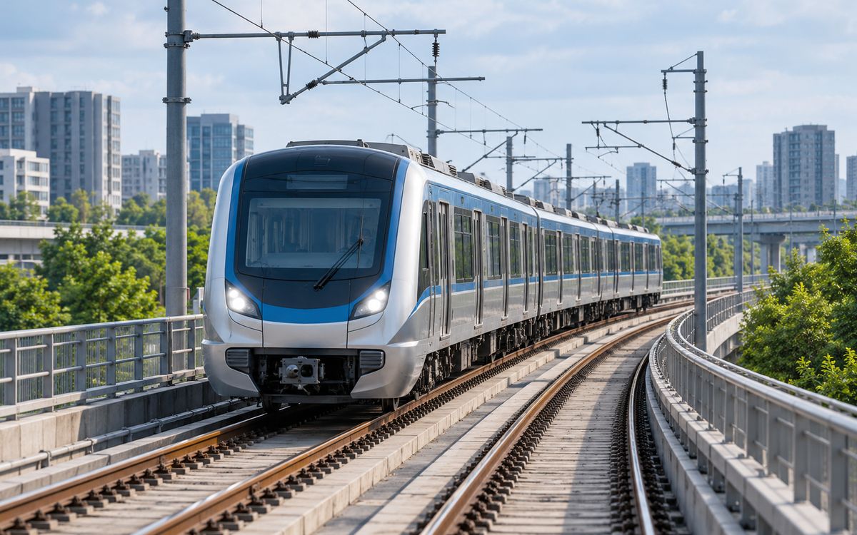
Rail and metro
Combination: running earth conductor (its own class) + traction substations ①
Through-earthing conductor under stray current: 0.8 mm throughout.
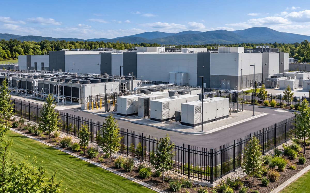
Data centres
Combination: campus rings ③ + substation ① + indoor copper
Outdoor grid replaceable; indoors solid copper by code.
Card images are illustrative application scenes (AI-generated), not photographs of our projects and not of any specific site; projects we have supplied are on the Projects page.
▸ Compare all project types at a glance
Copper layer, sizes and replaceability for 11 project types, including the cases where we recommend copper.
| Project type | Form | Copper layer, horizontal | Replaceable with CCS |
|---|---|---|---|
| Step-up substations 110–220 kV | Mesh grid ① | 0.60–0.80 mm | Yes – full replacement |
| Intake substations 110–220 kV (chemical, rail) | Mesh grid ① | 0.60–0.80 mm | Yes – full replacement |
| Transmission-line towers | Loop + radials ② | 0.60 mm (radial) | Yes – preferred over galvanised |
| PV plants (field) | Block rings + mains ①② | 0.60 mm | Yes – full replacement |
| PV plants (step-up substation) | Mesh grid ① | 0.60–0.80 mm | Yes – full replacement |
| Wind farms (turbine foundations) | Ring + radials ② | 0.60 mm | Yes – preferred |
| Wind farms (collector substation) | Mesh grid ① | 0.60–0.80 mm | Yes – full replacement |
| Chemical / oil & gas (plant grid) | Building rings ③ + mesh ① | 0.60–0.80 mm | Yes – full replacement |
| Telecom towers (remote) | Loop + radials ② | 0.60 mm | Yes – preferred |
| Rail and metro (running conductor) | Own class (through-earthing) | 0.80 mm | Yes – 0.8 mm specified |
| Data centres (outdoor grid) | Campus rings ③ + mesh ① | 0.60–0.80 mm | Yes – outdoor only; indoor solid copper |
The method behind these recommendations – definition, process, construction, shape, copper thickness, the IEEE 80 check, exothermic welding and the standards of each country – is in the selection and design guide.
Have a project in mind?
Send the conductor size, length, soil and fault current – two sizing options and the copper saving come back within 24–48 hours, free.
Request the free assessmentJust a quotation