
Wind farms
Copper-clad steel grounding system solutions · 4 of 8
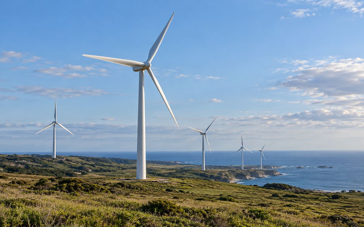
Illustrative application scene (AI-generated), not a project photograph.
1 Combination: substation + turbine foundations
Combination: one collector substation + twenty or thirty turbine foundations. Foundation earthing follows the tower radial form: a ring plus radials around the foundation, reliably bonded to the reinforcement, with lightning current setting the section; the collector substation follows the substation mesh grid; collector lines follow line rules. A wind farm uses about 10 000–30 000 m of earthing material in total. It is rarely bought separately – usually with the civil or electrical package – so it is best supplied as part of the contract.
2 Turbine foundation earthing: the tower form
A wind turbine is a tower over 100 m tall standing on a ridge; its earthing has the same roots as a transmission tower: use the foundation, run a ring around it, add radials by soil resistivity.
- The foundation reinforcement is the main electrode. IEC 61400-24 takes the reinforcement cage (type B foundation earth electrode) as the first choice; the ring-beam reinforcement is welded out to the ring electrode at two points at least, with an earthing terminal at the tower flange.
- Ring: 1 m outside the foundation, buried ≥ 0.8 m (≥ 0.5 m on hillsides, along the contour), Ø 12–14 annealed wire; Ø 16 × 2.5 m rods at the corners – only where the soil is deep enough; on a rock ridge where they will not go in, leave them out.
- Radials: where the ring does not meet the target, run 2–4 radials from the corners, length from the tower radial design table, each within the effective length of GB 50169 Table 3.7.5; on ridges run them along the contour, and where they can be led down to deeper soil, "lead out" – far more effective than lengthening in place.
- Target: turbine makers' specifications mostly ask for ≤ 4 Ω per turbine; IEC 61400-24 suggests ≤ 10 Ω. On a 2000 Ω·m ridge 4 Ω is neither achievable nor necessary; the tower approach – a permitted value graded by resistivity, with bonding and SPDs done properly – is far safer than a faked test value.
3 Lightning current sets the section
The turbine is the highest point on the site and its blades take several direct strikes a year; IEC 61400-24 takes 200 kA (10/350 μs) for LPL I. Power-frequency fault current is small by comparison (35 kV collector system, arc-suppression coil or low-resistance earthed, tens to hundreds of amperes). So the electrode section is set by lightning current and mechanical strength, not thermal stability: Ø 12–14 wire is enough, and what matters is the connection – tower to foundation to ring to radials must be exothermic welds or compression terminals, never bolted contact faces, which arc when loose.
Under lightning the effective length of a radial is much shorter than at power frequency (the lower the resistivity the shorter), and anything beyond it adds nothing to the impulse resistance – the reason radials should be "short rather than long, several rather than one", expanded in section 4 of the tower page.
4 Collector lines and the substation
- 35 kV overhead collector lines follow the tower page; with cable collectors, screens earthed at both ends tie every turbine earth to the substation grid – which lowers each turbine's resistance but also carries the substation's GPR to every tower base. Check the whole farm as one interconnected grid per IEEE 80 for transferred potential; the touch voltage at the tower door is the critical point.
- The collector substation (110 / 220 kV) is walked through the substation page: Ø 14–16, 0.8 mm grid, step and touch check, calculation issued for the design institute.
5 Ridges and coasts: corrosion
The two typical onshore sites are two corrosion environments:
| Site | Typical ρ (Ω·m) | Mechanism | Copper layer, horizontal |
|---|---|---|---|
| Ridges, plateaux | 500–3000 | weathered rock, acidic soil (pH 5–6), saturated in the wet season and bone-dry in the dry one – wet-dry cycling corrodes fast | 0.60 mm; 0.80 mm in forest soils of pH ≤ 4.5 |
| Coastal flats, islands | 2–50 | high Cl⁻, salt spray; zinc gone in 2–3 years | 0.80 mm (Q/GDW 12015 5.2.2.5: salt ≥ 1.5 % → copper) |
| Grassland, farmland | 50–300 | medium | 0.60 mm |
Offshore turbines are outside this page: monopiles and jackets are the electrode, seawater is 0.2 Ω·m, and buried earthing material is neither needed nor usable.
6 Quantities and how it is bought
A 50-turbine farm: ring plus radials 150–400 m per turbine (by resistivity), 10 000–20 000 m for the fifty; 3 000–4 000 m for the substation; 10 000–30 000 m of Ø 12–16 wire in all, plus 200–400 rods. Earthing is rarely tendered separately – it rides with the civil or electrical package – so our practice is to produce the earthing volume for the EPC or turbine maker: ring and radial lengths and a drawing for every turbine position from the surveyed resistivity, submitted together with the substation calculation.
7 What to send
Turbine positions and resistivity at each (or the geotechnical report – we estimate from the rock and soil types), the turbine maker's earthing specification (permitted resistance, terminal positions), collector type (overhead / cable), substation voltage and fault current, design life.
At a glance: typical selection
| Project type | Governing factor | Typical fault current / copper size | Soil and environment | Copper layer | Sizes (horizontal / vertical) | Replaceability |
|---|---|---|---|---|---|---|
| Wind farms (turbine foundations) | Lightning impulse; coastal / hill soils | Large lightning, small power-frequency / 70–95 mm² | Coastal salt spray, rocky hills | Coastal 0.8; inland 0.6 | Ø12–14 ring and radials / Ø16 rods | ★ Fully replaceable |
| PV / wind collector substation | Thermal stability | ≤ 25–33 kA @ 1 s / 70–120 mm² | As the field | 0.8 | Ø14–16 wire / Ø16–20 rods | Replaceable |
Have a project in mind?
Send the conductor size, length, soil and fault current – two sizing options and the copper saving come back within 24–48 hours, free.
Request the free assessmentJust a quotation