
Copper-clad steel earthing products: rods, wire, tape, strand
One factory, the full earthing conductor range. Browse our complete product catalog below – continuous-cast and electroplated processes, round wire, flat tape, stranded conductor and ground rods.
Detailed specifications
Round wireFlat tapeStrandRodsDeep-driving rodsExothermic weldingFormatsTechnical dataCapacity & lead timeOrdering terms
One card per product: continuous-cast on the left (our main range, 0.6 / 0.8 / 1.0 mm, annealed), electroplated on the right (on request, 0.25 mm, hard-drawn). Strand is continuous-cast only.
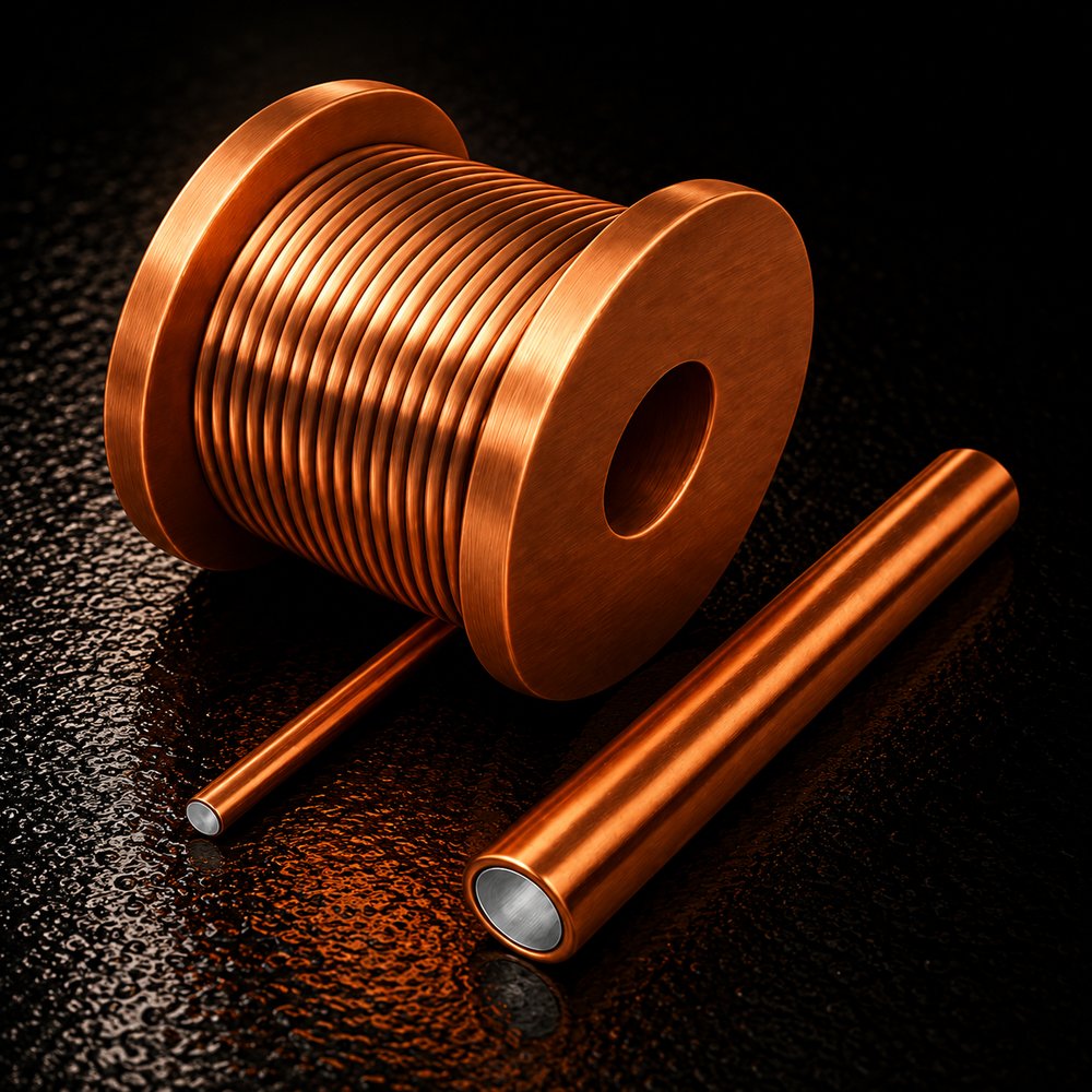
Continuous-cast round wire
Ø 8–18 mm, copper 0.6 / 0.8 / 1.0 mm, fully annealed (≥ 300 N/mm²). The horizontal grid conductor that replaces copper: Ø 12–14 in PV, telecom, industrial and rail sites; Ø 14–16 in distribution and 220 kV substations.
Specification
The steel core passes through molten copper and the copper crystallises onto it – a metallurgical bond with no interface gap – then the whole coil is annealed to the soft temper that DL/T 1312-2023 clause 4.2 recommends for horizontal conductor, so it bends on site. This is the product for medium- and high-corrosivity soil.
| Sizes | Ø 8, 10, 12, 14, 16, 18 mm; 100 m per reel standard, 200–1000 m on request |
|---|---|
| Copper layer | Nominal 0.60 / 0.80 / 1.00 mm |
| Tensile strength | ≥ 300 N/mm² (annealed horizontal-electrode class) |
| Bending | 90°, 3 bends – no cracks, fissures or pits in the copper |
| Copper–steel bond | 45° cone hammer test: no separation at the interface |
| Conductivity | 20–40 % IACS by size and copper – calculated values by size in the table below |
| Surface | Fine, uniform and smooth; no pinholes, pits, blisters, peeling, cracks or burns; no bare steel, loose copper or black spots |
| Type-tested sizes | Ø 12 / 0.6, Ø 14 / 0.8, Ø 16 / 0.6, Ø 18 / 0.8 mm; others on request |
| Model code | CCS CC 25-0.8-Φ16 (process – conductivity grade – copper – size) |
Electroplated round wire
Ø 8–18 mm, copper 0.25 mm, hard-drawn. For low-corrosivity soil, equipotential bonding and projects specified at 0.25 mm. Supplied, not recommended for horizontal grids in corrosive soil.
Specification
Electroplated copper on a hard-drawn steel core. A plated layer cannot be annealed – the heat would damage the bond – so the product is supplied hard. Supplied on request; for horizontal conductor in medium- or high-corrosivity soil we recommend the continuous-cast range (our position).
| Sizes | Ø 8, 10, 12, 14, 16, 18 mm; 100 m per reel standard |
|---|---|
| Copper layer | Nominal 0.25 mm |
| Tensile strength | ≥ 300 N/mm² (hard-drawn) |
| Bending | 90°, 3 bends – no cracks, fissures or pits in the copper |
| Copper–steel bond | 45° cone hammer test: no separation at the interface |
| Conductivity | 15–20 % IACS by size |
| Surface | Fine, uniform and smooth; no pinholes, pits, blisters, peeling, cracks or burns; no bare steel, loose copper or black spots |
| Type-tested sizes | Ø 12 / 0.25 and Ø 16 / 0.25 mm; others on request |
| Model code | CCS EP 15-0.25-Φ12 |
Supply position: why we supply 0.25 mm plated wire but do not recommend it →
Type-test report: Ø 12 / 0.6 mm continuous-cast wire, CNAS laboratory, full DL/T 1312-2023 programme passed (English PDF) ↓ · measured data
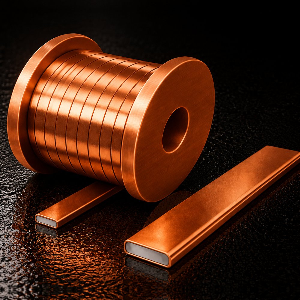
Continuous-cast flat tape
12 × 6 to 50 × 5 mm, copper 0.6 / 0.8 / 1.0 mm, annealed. For cross-sections above about 200 mm² where round wire becomes hard to lay.
Specification
Same process and temper as the round wire. Note that at equal copper content a tape keeps a thinner layer than round wire (round vs flat).
| Sizes | 12 × 6 to 50 × 5 mm (e.g. 30 × 4, 40 × 4, 50 × 5); reels or straight lengths |
|---|---|
| Copper layer | Nominal 0.60 / 0.80 / 1.00 mm |
| Tensile strength | ≥ 300 N/mm² (annealed horizontal-electrode class) |
| Bending | 90°, 3 bends – no cracks, fissures or pits in the copper |
| Copper–steel bond | 45° cone hammer test: no separation at the interface |
| Conductivity | 15–40 % IACS by section and copper |
| Surface | Fine, uniform and smooth; no pinholes, pits, blisters, peeling, cracks or burns; no bare steel, loose copper or black spots |
| Type-tested sizes | Type-tested on request for the size specified in a project |
| Model code | CCS CC 20-0.6-50×5 |
Electroplated flat tape
12 × 6 to 50 × 5 mm, copper 0.25 mm, hard-drawn. For undemanding sites and 0.25 mm specifications. Supplied, not recommended.
Specification
Electroplated copper on a hard-drawn steel core. A plated layer cannot be annealed – the heat would damage the bond – so the product is supplied hard. Supplied on request; for horizontal conductor in medium- or high-corrosivity soil we recommend the continuous-cast range (our position).
| Sizes | 12 × 6 to 50 × 5 mm; reels or straight lengths |
|---|---|
| Copper layer | Nominal 0.25 mm |
| Tensile strength | ≥ 300 N/mm² (hard-drawn) |
| Bending | 90°, 3 bends – no cracks, fissures or pits in the copper |
| Copper–steel bond | 45° cone hammer test: no separation at the interface |
| Conductivity | 15–20 % IACS by section |
| Surface | Fine, uniform and smooth; no pinholes, pits, blisters, peeling, cracks or burns; no bare steel, loose copper or black spots |
| Type-tested sizes | Type-tested on request for the size specified in a project |
| Model code | CCS EP 15-0.25-30×4 |
Supply position: why we supply plated tape but do not recommend it →
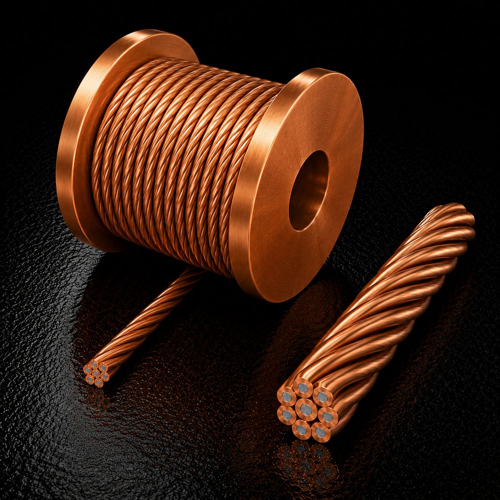
Copper-clad steel stranded conductor
70–240 mm², 30 % or 40 % IACS. Stranding is the harshest real-world test of the copper–steel bond – every strand is twisted and bent repeatedly.
Specification
Continuous-cast only. A plated layer does not have the bond to survive stranding – every wire is twisted and bent repeatedly – so we do not make electroplated strand. Specified by the per-wire minimum copper, which cannot be gauged after stranding (solid vs strand).
| Sizes | 70, 95, 120, 150, 185, 240 mm²; on reels |
|---|---|
| Copper layer | Nominal per wire, 0.60 / 0.80 mm |
| Tensile strength | ≥ 300 N/mm² per wire (bonding-conductor class) |
| Bending | 90°, 3 bends on the single wire – no cracks in the copper |
| Copper–steel bond | Single wire twisted to fracture per GB/T 239: no cracks, flaking or holes in the copper |
| Conductivity | Grade 30 or 40 % IACS (resistivity at 20 °C ≤ 5.75 / 4.31 × 10⁻⁸ Ω·m) |
| Surface | Fine, uniform and smooth; no pinholes, pits, blisters, peeling, cracks or burns; no bare steel, loose copper or black spots |
| Use | Earthing leads and flexible bonding; the buried electrode is better served by solid conductor |
| Test report | Factory test report per lot; type test on request for a project |
Supply position: why we do not recommend strand for buried electrodes →
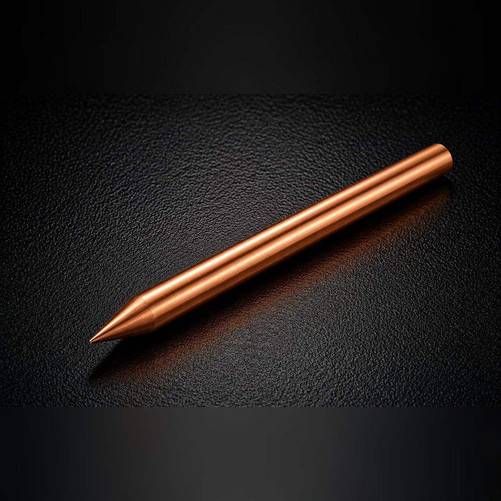
Continuous-cast ground rods
Ø 12–25 mm × 1.5 m, copper 0.6 / 0.8 mm, hard-drawn for driving; steel core ≥ 550 N/mm². The vertical electrode for medium- and high-corrosivity soil, from the same material system as the horizontal conductor.
Specification
A rod has to be driven, so it is supplied hard-drawn. Pointed, threaded or plain for coupling; for the threaded, coupled version see the deep-driving kit below.
| Sizes | Ø 12, 14, 16, 18, 20, 25 mm × 1.5 m standard (other lengths to order) |
|---|---|
| Copper layer | Nominal 0.60 / 0.80 mm |
| Tensile strength | ≥ 550 N/mm² (vertical-electrode class) |
| Bending | 30° at 40 diameters from the clamp, 20 bends – no cracks, fissures or pits in the copper |
| Copper–steel bond | One end cut to a 45° cone and the copper hammered off: no separation at the interface |
| Conductivity | 15–20 % IACS by size and copper |
| Surface | Fine, uniform and smooth; no pinholes, pits, blisters, peeling, cracks or burns; no bare steel, loose copper or black spots |
| Type-tested sizes | Ø 20 / 0.8 and Ø 25 / 0.8 mm, full DL/T 1312-2023 programme; other sizes on request |
| Model code | CCS CC 20-0.8-Φ20 |
Electroplated ground rods
Ø 12–25 mm × 1.5 m, copper 0.25 mm, hard-drawn; steel core ≥ 550 N/mm². The common international thin-layer rod specification (UL 467 / IEC 62561-2 class) for low-corrosivity soil and telecom sites – electroplating's home ground.
Specification
Electroplated copper on a hard-drawn steel core; the rod is driven, so the hard temper is what is wanted here. Pointed, threaded or plain for coupling.
| Sizes | Ø 12, 14, 16, 18, 20, 25 mm × 1.5 m standard (other lengths to order) |
|---|---|
| Copper layer | Nominal 0.25 mm (≥ 0.254 mm at any point where UL 467 is specified) |
| Tensile strength | ≥ 550 N/mm² (vertical-electrode class) |
| Bending | 30° at 40 diameters from the clamp, 20 bends – no cracks, fissures or pits in the copper |
| Copper–steel bond | One end cut to a 45° cone and the copper hammered off: no separation at the interface |
| Conductivity | 15 % IACS |
| Surface | Fine, uniform and smooth; no pinholes, pits, blisters, peeling, cracks or burns; no bare steel, loose copper or black spots |
| Type-tested sizes | Type-tested on request for the size specified in a project |
| Model code | CCS EP 15-0.25-Φ16 |
Kits, jointing and supply
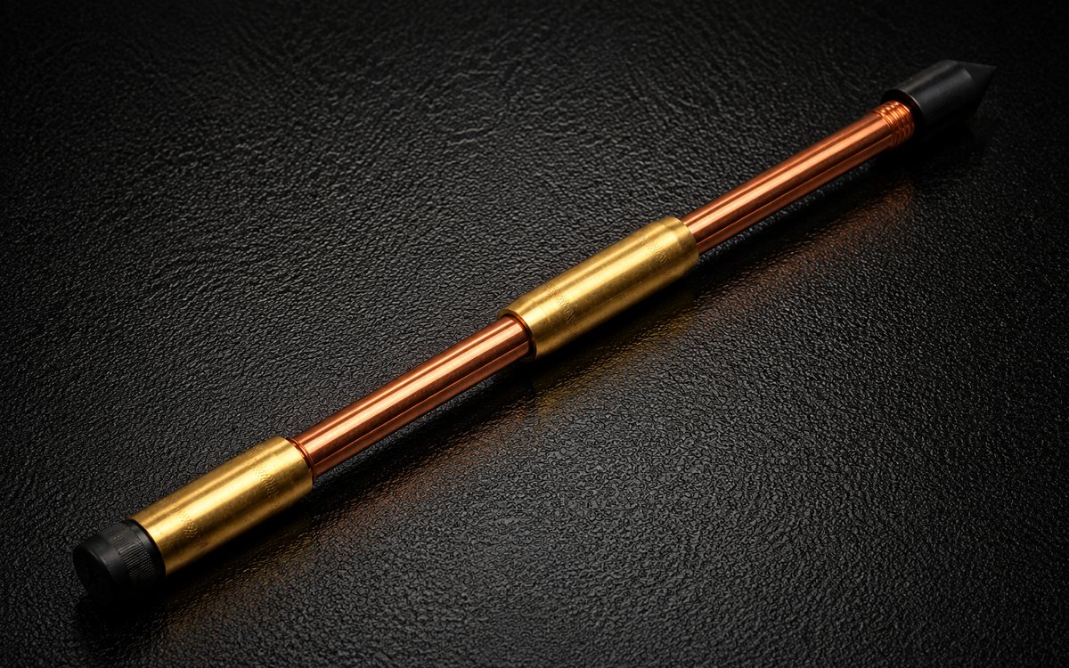
Extensible deep-driving ground rods
The same copper-bonded rod, threaded at both ends and coupled section by section to reach stable, moist, low-resistivity soil – deep electrodes where the surface layer is dry, rocky or high in resistivity. Supplied as a kit: rods, brass couplers, hardened driving tip and driving head.
Specification
Rods are driven one after another: the driving head takes the hammer, the brass coupler joins the next section without exposing bare steel, the steel tip opens the way. Sections can be coupled to the depth the soil requires, and the copper layer and steel core are the same as the standard rod.
| Rod | Ø 14–25 mm × 1.5 m (other lengths to order), rolled thread at both ends; copper and core as the standard rod |
|---|---|
| Coupler | Brass (copper alloy) threaded coupler, full-section; the rod-to-rod joint stays inside the coupler and keeps its copper cover |
| Driving tip | Hardened steel, pointed, threaded onto the first section |
| Driving head | Steel driving head / stud screwed onto the top section to protect the thread under the hammer; removed on reaching depth |
| Copper layer | Nominal (0.25 / 0.60 / 0.80 mm) |
| Tensile strength | ≥ 550 N/mm² (vertical-electrode class) |
| Bending | 30° at 40 diameters from the clamp, 20 bends – no cracks, fissures or pits in the copper |
| Copper–steel bond | One end cut to a 45° cone and the copper hammered off: no separation at the interface |
| Conductivity | 15–40 % IACS by size and copper |
| Connection to the grid | Exothermic weld or clamp at the top section; welding moulds supplied to match |
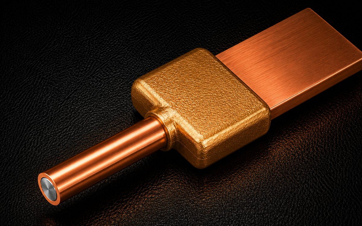
Exothermic welding
Graphite moulds, weld powder and accessories for copper-to-CCS and CCS-to-CCS joints. Joint quality assessed to DL/T 1342-2014; smooth, full-coverage welds.
Specification
Graphite moulds by joint type (straight, tee, cross, rod-to-conductor, conductor-to-steel) and weld powder in single-shot charges matched to the mould and conductor size. Welding procedure and attendance at the first joints are part of the engineering service.
| Joint acceptance | Full enclosure of the parent conductor; smooth surface, no porosity or cracks |
|---|---|
| Electrical | DC resistance of the joint ≤ 1.1 × an equal length of parent conductor |
| Mechanical | Tensile strength of the joint ≥ parent conductor |
| Where hot work is restricted | IEEE 837-qualified compression connectors (exothermic welding guide) |
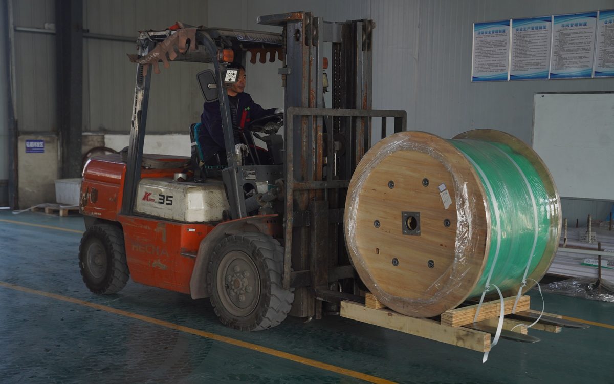
Formats and packing
Coils, straight lengths or cut-to-order. ISO 9001 factory; full batch traceability from electrolytic copper and steel rod to finished coil.
Technical data – continuous-cast round wire (calculated)
Conductivity varies with diameter and copper thickness: at 0.8 mm copper, Ø8 is about 43% IACS and Ø16 about 28%. The table is calculated by the bimetallic-conductor method of IEEE Std 80-2013 (clause 11.3), with the Table 1 material constants: annealed copper 1.72 μΩ·cm (100% IACS) and steel 1020 15.90 μΩ·cm (10.8% IACS); densities 8.96 and 7.85 g/cm³ for preliminary selection and submittal estimates; the DL/T 1312 grade is the highest of the five classes not exceeding the unrounded value; measured values are given in the factory test report for each lot. Sizes already type-tested to DL/T 1312: Ø 12 / 0.25, Ø 12 / 0.6, Ø 14 / 0.8, Ø 16 / 0.25, Ø 16 / 0.6, Ø 18 / 0.8 (horizontal) and Ø 20 / 0.8, Ø 25 / 0.8 (rods); all other sizes, including Ø 16 / 0.8 and every 1.0 mm size, are calculated values and are type-tested on request for a project (see Test evidence). The same data with materials, tests, packing and ordering terms: product data sheet (PDF).
| Ø mm | Copper mm | Total section mm² | Copper section mm² | ≈ Conductivity %IACS | DL/T 1312 grade | ≈ DC resistance Ω/km (20 °C) | ≈ Mass kg/m | of which copper kg/m |
|---|---|---|---|---|---|---|---|---|
| 8 | 0.6 | 50 | 13.9 | 35.6 | 30% | 0.962 | 0.41 | 0.12 |
| 8 | 0.8 | 50 | 18.1 | 42.9 | 40% | 0.797 | 0.41 | 0.16 |
| 8 | 1.0 | 50 | 22.0 | 49.8 | 40% | 0.687 | 0.42 | 0.20 |
| 10 | 0.6 | 79 | 17.7 | 30.9 | 30% | 0.708 | 0.64 | 0.16 |
| 10 | 0.8 | 79 | 23.1 | 37.1 | 30% | 0.591 | 0.64 | 0.21 |
| 10 | 1.0 | 79 | 28.3 | 42.9 | 40% | 0.510 | 0.65 | 0.25 |
| 12 | 0.6 | 113 | 21.5 | 27.8 | 25% | 0.548 | 0.91 | 0.19 |
| 12 | 0.8 | 113 | 28.1 | 33.0 | 30% | 0.461 | 0.92 | 0.25 |
| 12 | 1.0 | 113 | 34.6 | 38.1 | 30% | 0.400 | 0.93 | 0.31 |
| 14 | 0.6 | 154 | 25.3 | 25.5 | 25% | 0.439 | 1.24 | 0.23 |
| 14 | 0.8 | 154 | 33.2 | 30.0 | 30% | 0.372 | 1.25 | 0.30 |
| 14 | 1.0 | 154 | 40.8 | 34.5 | 30% | 0.324 | 1.25 | 0.37 |
| 16 | 0.6 | 201 | 29.0 | 23.7 | 20% | 0.361 | 1.61 | 0.26 |
| 16 | 0.8 | 201 | 38.2 | 27.8 | 25% | 0.308 | 1.62 | 0.34 |
| 16 | 1.0 | 201 | 47.1 | 31.7 | 30% | 0.270 | 1.63 | 0.42 |
| 18 | 0.6 | 254 | 32.8 | 22.3 | 20% | 0.303 | 2.03 | 0.29 |
| 18 | 0.8 | 254 | 43.2 | 26.0 | 25% | 0.260 | 2.05 | 0.39 |
| 18 | 1.0 | 254 | 53.4 | 29.5 | 25% | 0.229 | 2.06 | 0.48 |
The technical requirements (copper measuring points, tensile, bending, bond, conductivity grades, high-current and electrical-corrosion limits) and the type-test programme are on the Test evidence page. Copper for comparison (annealed): 50 mm² 0.345 Ω/km, 0.45 kg/m; 70 mm² 0.246 Ω/km, 0.62 kg/m; 95 mm² 0.181 Ω/km, 0.85 kg/m; 120 mm² 0.144 Ω/km, 1.07 kg/m. Data for 0.25 mm sizes, flat tape, strand and rods on request.
Supply, capacity and lead time
| Destination | Sea transit (from Shanghai) | Order to cargo available at destination (new size, incl. clearance) |
|---|---|---|
| Vietnam / Philippines / Malaysia | 6–12 days | ≈ 5 weeks |
| Indonesia / Thailand | 9–14 days | ≈ 5–6 weeks |
| UAE (Jebel Ali) | 20–25 days | ≈ 7 weeks |
| Saudi Arabia (Dammam) / Qatar | 25–30 days | ≈ 8 weeks |
| Pakistan / Bangladesh | 15–25 days | ≈ 6–7 weeks |
| US West Coast | 15–20 days | ≈ 7 weeks |
| US Gulf / East Coast | 35–45 days | ≈ 10 weeks |
| UK / Northern Europe | 32–40 days | ≈ 9–10 weeks |
| Australia | 20–28 days | ≈ 8 weeks |
| Brazil / Chile | 35–45 days | ≈ 10 weeks |
| East Africa (Mombasa) | 25–32 days | ≈ 8–9 weeks |
| West Africa (Lagos) | 40–50 days | ≈ 11 weeks |
Order to cargo available = 2 weeks production + about 1 week factory-to-Shanghai, booking and export clearance + sea transit + about 1 week destination clearance. Transit times are typical ranges; the sailing schedule at booking governs.
Ordering terms
| Item | Terms |
|---|---|
| Samples | Sample lengths (≤ 1 m) of standard sizes free of charge, freight collect; samples to your specification on request, by air in 5–7 days. |
| Minimum order | Standard sizes: round wire / flat tape 300 m (3 reels), strand 300 m, rods 50 pieces; non-standard sizes 1,000 m (set-up required, 2 weeks ex-works). Trial orders welcome; project orders are most economical by the 20' container (about 15 km of Ø 16). |
| Price basis | FOB Shanghai (Incoterms 2020) by default; CFR / CIF to a named port, or EXW Mingguang, Anhui, quoted on request. |
| Payment | T/T: 30 % deposit, 70 % before shipment; irrevocable L/C at sight accepted for orders of US$ 50,000 and above; samples and small orders paid in full in advance. |
| Packing | Round wire 100 m per wooden reel (200–1000 m on request); flat tape and strand on wooden reels; rods bundled or crated; all wood packaging heat-treated and marked to ISPM 15. |
| Documents | Commercial invoice, packing list, bill of lading, certificate of origin (general or preferential), factory test report for the lot, type-test report summary; manufacturer's declaration of conformity for EU projects on request. |
Have a project in mind?
Send the conductor size, length, soil and fault current – two sizing options and the copper saving come back within 24–48 hours, free.
Request the free assessmentJust a quotation