
Data centres
Copper-clad steel grounding system solutions · 8 of 8
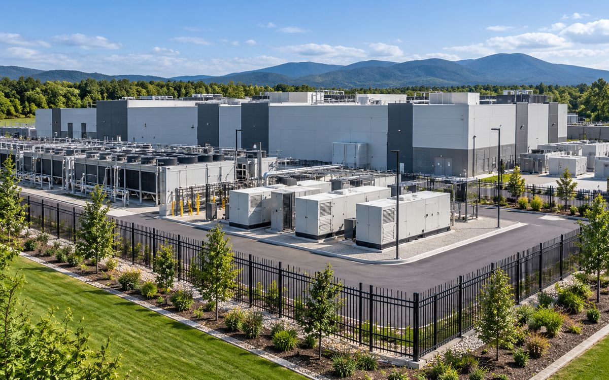
Illustrative application scene (AI-generated), not a project photograph.
1 Combination: campus rings + substation + indoor copper
Combination: campus rings + substation + indoor copper. The campus ring and each building ring follow building ring earthing and are interconnected; the on-site substation follows the substation mesh grid; the hall equipotential mesh, earthing bars and any underground substation are pure copper per DL/T 2650-2023 – copper-clad steel replaces the part in the ground, not the part in the hall.
2 Campus and building rings
The buried part of a data centre follows building ring earthing (basic form ③), only denser and with more interconnections:
- Every data hall, power building and generator building gets a ring 1 m outside the wall, buried ≥ 0.8 m, Ø 12–14 annealed wire, with Ø 16 × 2.5 m rods at the corners and down-leads, welded at many points to the foundation reinforcement – piles and raft reinforcement are the largest natural electrode on the campus, and bonding them does more than anything else you could bury.
- Building rings are interconnected by a campus ring and mains, tied to the earths of cooling towers, fuel tanks, fences and generator exhaust stacks into one campus grid.
- Down-lead to electrode joints exothermically welded; at least two test pits per building, measured yearly in operation.
3 The on-site substation
Large campuses build their own 110 / 220 kV substation, walked through the substation page: fault current sets the section, step and touch are checked, and once tied to the campus grid the transferred potential is checked – every equipment earthing bar in the halls hangs on the same grid, so the substation's GPR appears on every rack during a fault. The GPR therefore has to be held lower than at an ordinary station; Rg under 0.5 Ω and GPR under 2 kV are common targets. Underground or semi-underground substations are pure copper per DL/T 2650-2023 5.1.1.7.
4 Indoors: the equipotential mesh in copper
The indoor system – main earthing bar (MGB), floor earthing bars, the hall equipotential mesh (MESH-BN, copper tape or cable on a 0.6–3 m grid under the raised floor), rack earths and signal reference grids – is pure copper per TIA-942, IEC 62305-4 and GB 50174. Not because of conductivity (copper-clad steel would do) but for two reasons: DL/T 2650-2023 5.1.1.7 requires pure copper indoors and underground, and an indoor mesh is crimped and re-connected repeatedly, which bare copper tape and cable suit far better. Copper-clad steel replaces the part in the ground, not the part in the hall. On data-centre projects we supply the buried rings, rods, exothermic welding and the down-leads to the MGB, and match the owner's copper specification indoors.
5 Targets: 1 Ω and low impedance
- Earth resistance: GB 50174 sets the resistance of a shared protective, functional and lightning earthing system at the lowest of the systems sharing it, and owners' specifications usually write ≤ 1 Ω. On a campus of several hectares with dense piling 1 Ω is not hard; what actually matters is the substation GPR control above.
- Low impedance over low resistance: a data centre's earthing has to deal with lightning and switching transients at high frequency, and the potential difference at equipment is set by the impedance of the earthing path (length, loop area), not by the power-frequency resistance a tester reads. So rings closed, down-leads many, paths short – a layout question, not a material one.
- What not to do: drill deep wells or bury modules on the campus "for the 1 Ω". With foundation reinforcement, rings and the substation grid tied together, the resistance will only be lower than required.
6 What to send
Campus plot plan and foundation types (piles / raft), on-site substation voltage and fault current, soil resistivity, the owner's earthing specification (resistance, MGB positions, hall mesh specification), design life.
At a glance: typical selection
| Project type | Governing factor | Typical fault current / copper size | Soil and environment | Copper layer | Sizes (horizontal / vertical) | Replaceability |
|---|---|---|---|---|---|---|
| Data centres | Low impedance, bonding, corrosion | By supply voltage / 95–120 mm² | Campus fill | Outdoor 0.6–0.8; indoor copper per code | Outdoor Ø12–14 wire / Ø16 rods | Outdoor replaceable; indoor copper |
Have a project in mind?
Send the conductor size, length, soil and fault current – two sizing options and the copper saving come back within 24–48 hours, free.
Request the free assessmentJust a quotation