
PV plants
Copper-clad steel grounding system solutions · 3 of 8
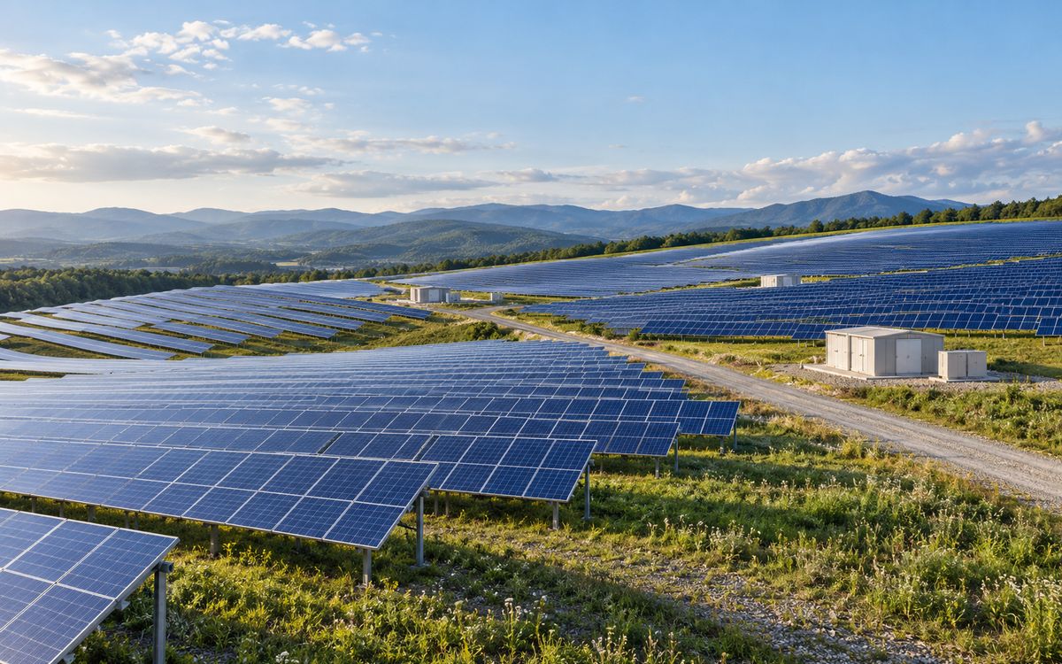
Illustrative application scene (AI-generated), not a project photograph.
PV field: block rings plus mains into a mesh (one ring per block, mains along roads / cable trenches, tied into the substation grid)
1 Combination: array field + substation
Combination: array field "mesh plus ring" + step-up substation. The field is divided into blocks, each with a ring, the blocks tied together by main conductors into a mesh, with structures, combiner boxes and inverters bonded to the nearest branch; the step-up substation is a standard substation mesh grid. A 100 MW PV plant covers about 200 ha, fifteen times a 2 × 350 MW thermal plant, with ten times as many connection points – hence the largest segment by kilometres, but with small sections.
Actual bill of materials for a 100 MW-class plant: Ø 12 copper-clad steel main conductor 17 729 m and branches 19 032 m; 150 copper-bonded rods Ø 12.7 × 2.44 m; 78 exothermic mould sets (straight, tee and cross; wire-to-tape and wire-to-rod transitions); weld powder 2 488 × 115, 3 900 × 150 and 490 × 200 charges. Structure connections can be prefabricated tinned copper-clad steel to galvanised-tape welded pieces, made in the warehouse and fitted on site.
The down-lead at the soil–air boundary sees the greatest oxygen-concentration difference and is where galvanised steel corrodes first; PV plants have few operators, rely on remote monitoring that cannot see earthing corrosion, and retrofitting means trenching across hundreds of hectares between modules – the core reason PV plants use copper-clad steel.
2 Laying out the field grid
Earthing a PV field is not a resistance problem; it is an equipotential and coverage problem. DC-side fault current is limited by the inverters to 1.1–1.5 times rated current – tens to a hundred-odd amperes – which any conductor size carries. What has to be achieved is that every structure row, combiner box and inverter sits on one equipotential body, with no floating metal when lightning strikes.
- Rings per block: divide the field into blocks (usually one inverter or one sub-array each) and run a ring electrode around the outside of each block, buried ≥ 0.6 m (≥ 0.8 m in farmland, below the plough layer).
- Mains into a mesh: tie the block rings together with main conductors along cable trenches or roads, bonded to trench supports, fences and kiosk enclosures as they pass; the mesh size equals the block size (tens of metres) – there is no need for the 5–10 m densification of a substation.
- Structure bonding: every row bonded to the ring or branch at two points at least, every 20–30 m on long rows; the posts themselves are natural electrodes – driven piles go 1.5–2.5 m into the ground and there are tens of thousands of them, and using them beats driving extra rods by a wide margin.
- Combiner boxes, inverters, kiosks: one or two Ø 14–16 × 2.4 m rods at each foundation, tied to the branch – not for resistance but to give lightning current a local path to earth.
- Air termination: the structures themselves act as air terminals; no separate masts (they shade modules). The posts are the down-conductors, so the post-to-ring joint is a lightning path: exothermic weld or purpose-made clamp, never a bolted splice.
3 Targets: resistance and grading
Chinese design practice under GB 50797 takes the field earth resistance at ≤ 4 Ω; on a grid of hundreds of hectares this is met almost automatically – by the IEEE 80 estimate R ≈ ρ/(4r), a 200 ha field (radius about 800 m) on 1000 Ω·m desert comes to 0.3 Ω. The field never needs resistance-reducing measures; anyone selling "resistance-reducing products" for a PV field is selling something useless.
Two things do need checking: ① step and touch voltage at the step-up substation (section 6); ② step voltage at the field perimeter and roads – once field and substation grids are tied together, the substation's ground potential rise reaches the field edge, and the potential difference where a passer-by stands outside the fence has to be checked per IEEE 80 clause 16.5, usually settled by a grading ring 1 m outside the fence.
4 Soil, corrosion and theft
PV plants are built on land nobody else wants: desert, salt flats, tidal flats, mining subsidence, fish ponds. These are exactly the "high corrosivity" soils of DL/T 2650-2023 Table 1. By its material ladder:
| Site | Typical ρ (Ω·m) | Corrosivity | Copper layer, horizontal | Notes |
|---|---|---|---|---|
| Desert, gravel | 500–3000 | low–medium | 0.60 mm | dry and slow, but salts activate in the wet season |
| Farmland, forest | 50–300 | medium | 0.60 mm | fertiliser and pesticide swing the pH; bury below the plough layer |
| Salt flats, inland salt lakes | 5–50 | high | 0.80 mm | high Cl⁻; Q/GDW 12015 5.2.2.5: salt ≥ 1.5 % → copper |
| Tidal flats, coast, fish ponds | 2–30 | high | 0.80 mm | saturated all year; down-leads fail first at the soil–air line |
| Mining subsidence, tailings | 30–200 | high (acidic) | 0.80 mm or copper | pH ≤ 4.5: ≥ 1.0 mm per Q/GDW 12015 5.2.2.6 |
Three lessons:
- The soil–air line corrodes first. The post-to-electrode joint and the 30 cm of down-lead above ground see the greatest oxygen-concentration difference; galvanised steel rusts through there in 3–5 years. Either weld copper-clad steel straight to the post and coat the joint, or use prefabricated tinned copper-clad steel to galvanised-tape transition pieces.
- Nobody walks a PV plant. Operation relies on remote monitoring, which cannot see earthing corrosion; a retrofit means trenching hundreds of hectares under the modules, and the labour plus module damage cost an order of magnitude more than the material saved. That is the core reason a PV plant takes 0.6/0.8 mm rather than 0.25 mm.
- Theft. Bare copper tape and cable in open country are the first things to go; copper-clad steel cannot be stripped and has negligible scrap value – the direct answer to field theft.
5 Quantities and bill of materials
A 100 MW-class plant covers about 200 ha, fifteen times a 2 × 350 MW thermal plant, with ten times the connection points – PV is the largest segment by kilometres, with small sections. The actual bill of materials from one 100 MW-class plant we supplied:
| Item | Specification | Quantity | Use |
|---|---|---|---|
| Copper-clad steel wire, mains | Ø 12, annealed | 17 729 m | between blocks, along cable trenches |
| Copper-clad steel wire, branches | Ø 12, annealed | 19 032 m | block rings, structure branches |
| Copper-bonded rods | Ø 12.7 × 2.44 m | 150 | at combiner boxes, inverters, kiosks |
| Exothermic moulds | straight / tee / cross; wire-to-tape and wire-to-rod | 78 sets | about 50–80 welds each |
| Weld metal | #115 / #150 / #200 | 2 488 / 3 900 / 490 charges | by joint type |
| Prefabricated transitions | tinned copper-clad steel to galvanised tape | per row count | made in the warehouse, fitted on site |
Rule of thumb: about 350–400 m of horizontal conductor, 1.5 rods and 70 exothermic joints per MW; add 20–30 % on hill sites and scattered plots. An exothermic joint takes 3–5 minutes; a three-man crew makes 60–80 a day, so the earthing of a 100 MW plant is done in 2–3 weeks.
6 Tying the field to the substation
Walk the step-up substation through the substation page: the 110 / 220 kV single-phase fault current sets the grid section (usually Ø 14–16, 0.8 mm), and step and touch voltages are checked per IEEE 80. The field grid and the substation grid must be one grid – left separate, a fault produces a dangerous potential difference between them, and the collector-cable screens carry it into the kiosks. Tied together, the substation resistance becomes very low (the field is large) but the GPR spreads over the whole field, which is why section 3 checks perimeter step voltage. We issue the substation calculation to IEEE 80 for the design institute to check.
7 Field-grid calculator
PV field earth resistance (IEEE 80 eq. 52 plus conductor-length term)
R ≈ ρ/(4r) + ρ/L, r = √(A/π). For showing that the field needs no resistance reduction; for the substation's Rg, GPR, step and touch voltages use the calculator on the substation page.
8 What to send, common mistakes
Send: capacity and plot coordinates (we estimate the soil type from them), step-up voltage and fault current, structure type (fixed / tracker, piles / concrete), design life, whether theft resistance is a requirement.
Common mistakes: ① measuring resistivity at one point by the substation – 200 ha needs 5–10 points, salt flat and dune can differ a hundredfold; ② buying "resistance-reducing products" for the field (useless, and corrosive); ③ bolted splices as lightning paths on structures (arc once loose); ④ field and substation grids not tied together; ⑤ 0.25 mm plated wire as the horizontal electrode on a salt flat – it belongs in dry, low-corrosivity, maintainable sites, not here (see position 1).
At a glance: typical selection
| Project type | Governing factor | Typical fault current / copper size | Soil and environment | Copper layer | Sizes (horizontal / vertical) | Replaceability |
|---|---|---|---|---|---|---|
| PV plant (array field) | Bonding, lightning, theft; long runs | Small (inverter-limited) / 50–70 mm² | Desert, saline flats, farmland, tidal land | Inland 0.6; coastal / saline 0.8 | Ø10–12 wire / Ø14–16 rods | ★ Fully replaceable |
| PV / wind collector substation | Thermal stability | ≤ 25–33 kA @ 1 s / 70–120 mm² | As the field | 0.8 | Ø14–16 wire / Ø16–20 rods | Replaceable |
Have a project in mind?
Send the conductor size, length, soil and fault current – two sizing options and the copper saving come back within 24–48 hours, free.
Request the free assessmentJust a quotation