
Substations
Copper-clad steel grounding system solutions · 1 of 8
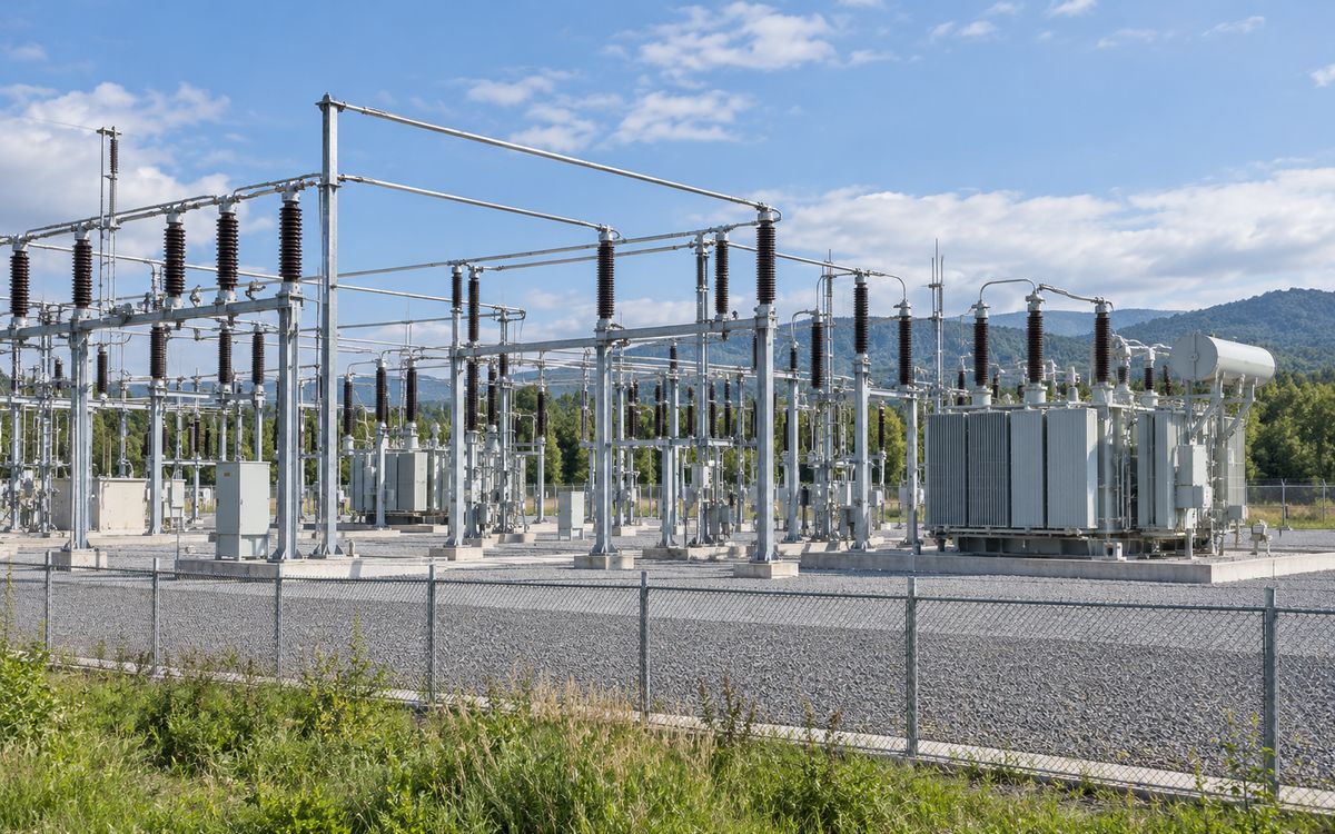
Illustrative application scene (AI-generated), not a project photograph.
Basic form ①: substation mesh grid (meshes, perimeter rods, rods under equipment)
The principle first: Earth resistance depends only on the shape and area of the electrode and the soil resistivity, not on the material; the material decides the service life. This page is about the first half – how the resistance, step voltage and touch voltage of a substation grid are designed; material and copper layer appear only in section 6. Everything follows GB/T 50065-2011 and IEEE Std 80-2013 and can be recalculated.
1 What this project has to achieve
A substation grid does four jobs at once, and a design that misses one is not a design:
| Goal | Governing criterion | Basis |
|---|---|---|
| Carry fault current into the earth | Earth resistance R: generally R ≤ 2000 / I (I = fault current entering the grid, A); Chinese practice at 110 kV and above commonly requires ≤ 0.5 Ω; may be relaxed with justification but never above 5 Ω, with isolation measures | GB/T 50065-2011 |
| Keep people safe | Touch voltage Et and step voltage Es within tolerable limits, which depend on fault duration ts, surface-layer resistivity ρs and thickness hs | IEEE Std 80-2013 clause 8; GB/T 50065-2011 |
| Survive the fault without fusing | Conductor section passes the thermal check (Akcmil = I·Kf·√tc) | IEEE 80 clause 11.3; see precise selection |
| Reach the design life | Copper thickness by soil corrosivity: 0.6 mm medium, 0.8 mm high; pure copper in indoor and underground substations | DL/T 2650-2023 Table 4, clause 5.1.1.7 |
The first three are decided by shape, area, soil and section, and have nothing to do with "galvanised steel or copper-clad steel"; only the fourth is a material question. Mixing the two is the most common mistake in earthing design, in China and abroad.
2 Step one: survey, not material
Earth resistance R = ρ × F(shape). Quadrupling the grid area halves the resistance; reducing the resistivity to a quarter cuts it by 75 %. So what decides a substation grid is, first of all, whether the soil resistivity was measured properly and layered correctly.
- Method: Wenner four-pin, spacing stepped from 1 m to one or two times the site length, in at least two orthogonal directions; the apparent-resistivity curve is inverted to a two- or three-layer model. A geotechnical report is no substitute – boreholes give lithology, not resistivity.
- Depth: the layers that govern a large grid lie tens of metres down, sometimes more than a hundred. Fixing a scheme on data to 10–20 m is the common cause of the wasted money in the cases below.
- Criterion: reflection factor K = (ρ2 − ρ1) / (ρ2 + ρ1). K negative (lower layer less resistive): long vertical electrodes and deep wells work. K positive: anything driven downwards is wasted; extend outwards instead.
The first question in our free assessment is "is there layered resistivity data?" If not, we tell you how to measure and how deep, instead of quoting material.
3 Grid resistance: estimate and calculate
Estimate: GB/T 50065-2011 commonly uses R ≈ 0.5 ρ / √A (A = grid area, m²). It runs about 13 % above the equal-area disc formula – conservative, good for judging whether a conventional grid is enough.
Calculate: the Sverak expression of IEEE Std 80-2013 clause 14.2, including total conductor length LT and burial depth h:
Worked example: site 100 m × 100 m, uniform soil ρ = 80 Ω·m, 10 m × 10 m mesh (2200 m of conductor), depth 0.6 m: estimate 0.40 Ω, Sverak 0.39 Ω – meets 0.5 Ω without extending the grid, but still has to pass the step and touch check of section 4. At ρ = 300 Ω·m the same grid only reaches 1.5 Ω and the sequence of section 5 applies.
Grid resistance and tolerable voltages – quick calculator
Uniform-soil approximation; layered soil needs an equivalent resistivity from the inverted model or a numerical method. Tolerable voltages per IEEE 80-2013 clauses 8.3 / 8.4 (50 kg body). For preliminary judgement, not a substitute for the design report.
4 Step and touch voltage
A passing resistance does not mean a safe grid. During a fault the grid rises to GPR = IG · Rg; a person touching an enclosure with feet on the ground sees the mesh voltage Em; between two feet is the step voltage Es. The IEEE 80 logic is:
- Compute the tolerable values first. Etouch50 = (1000 + 1.5 Cs ρs) · 0.116 / √ts; Estep50 = (1000 + 6 Cs ρs) · 0.116 / √ts. Cs is the surface-layer derating factor, Cs = 1 − 0.09(1 − ρ/ρs) / (2hs + 0.09).
- Then the actual values. Mesh voltage Em = ρ Km Ki IG / LM; step voltage Es = ρ Ks Ki IG / LS (IEEE 80 clause 16.5). Smaller meshes, more vertical electrodes and more conductor all lower Em.
- The grid passes only when Em ≤ Etouch50 and Es ≤ Estep50. If not, in order of cost: thicker crushed-rock layer, denser perimeter meshes, longer vertical electrodes along the perimeter, larger grid.
Worked example: the 100 m × 100 m grid above with a crushed-rock layer of ρs = 3000 Ω·m, 0.1 m thick, ts = 0.5 s: Cs = 0.70, Etouch50 ≈ 680 V, Estep50 ≈ 2220 V. At 10 kA grid current GPR ≈ 3.9 kV; mesh voltage is typically 15–30 % of GPR, i.e. 600–1200 V – the corner meshes are likely to fail, which is why substation grids are densified at the edges and fitted with long vertical electrodes.
Three blind spots: ① resistance calculated, voltages not; ② the crushed-rock layer treated as optional – it raises the tolerable values two- to threefold and is the cheapest safety measure there is; ③ transferred potential to the outside (telecom lines, LV feeders, pipes, rails) left un-isolated.
5 The right order for lowering resistance
For power-frequency resistance: one-dimensional (a straight line) is most efficient, two-dimensional (a plane) next, three-dimensional (a solid) least. To reach the same resistance, a solid block electrode needs hundreds of thousands of times the material of a round conductor, a plate hundreds of times, a mesh three to four times a cross. A substation needs a mesh for potential grading; but whatever is added on top of the mesh should come in this order:
- Fill the site first. If the conventional grid reaches the target, stop there; meshes need not be finer than 10 m × 10 m – finer meshes add almost nothing to resistance, only to grading.
- Then extend or lead out. Where low-resistivity ground exists outside the fence (river flats, farmland), radial electrodes led out to it are the most economical measure; 40–100 m each, by resistivity.
- Long vertical electrodes. A ring of 2.5 m rods around a large grid does almost nothing (shielding); the IEEE 80 examples use 7.5–10 m rods. The deep-driving coupled rod kit exists for this: driven section by section to 10–20 m into stable, moist deep soil. Condition: K negative in section 2.
- Deep wells and deep-buried radials. Only where the deep layer is genuinely less resistive (K clearly negative) and there is no room to extend; wells where the upper layer is the resistive one, deep horizontal radials where the lower is. Survey before drilling – or see section 8.
- Not used: anything that "reduces resistance" by chemical backfill or block electrodes – the least efficient shape at the highest price, and banned by most Chinese utilities. We supply conductors and connections only.
Typical layout and quantities (Chinese project statistics)
Outdoor substations run from 70 m × 70 m to 200 m × 300 m, with 5 × 5, 10 × 10 or 20 × 20 m meshes over the site, vertical electrodes along the perimeter and under transformers where needed; 500 kV stations commonly use 15 × 15 m meshes densified at the corners. A 220 kV station in high-resistivity soil, meshed at 5 × 5 m for grading, can use more conductor than a 500 kV one.
| Voltage | Outdoor: horizontal (m) | Outdoor: rods | Indoor: horizontal (m) | Indoor: rods | Wire diameter (mm) |
|---|---|---|---|---|---|
| 110 kV | 2 800 | 120 | 800 | 150 | 12 |
| 220 kV | 3 600 | 140 | 1 200 | 180 | 12 / 14 |
| 330 kV | 5 000 | 200 | — | 230 | 14 / 16 |
| 500 kV | 9 000 | 280 | 2 500 | 320 | 16 / 18 |
| 500 kV converter station | 22 000 | 340 | — | — | 18 |
| 800 / 1000 kV | 27 000 | 440 | — | — | 18 |
Overall statistics from our Chinese project experience; actual quantities depend on site, resistivity and grading (a 110 kV station in Yunnan used 10 000 m). Indoor substations are small but well funded and are generally built in pure copper; lightning belts, down-leads and indoor equipotential connections can be copper-clad steel – about 2 000 m for a 110 kV indoor station.
6 Material and copper layer
Only now does material come in. Per DL/T 2650-2023 clause 5.1.1.5 and Table 4: hot-dip galvanised steel in negligible and low corrosivity; copper-clad steel with ≥ 0.6 mm copper in medium; copper or copper-clad steel with ≥ 0.8 mm in high; pure copper in coastal, chemical and saline areas with salt ≥ 1.5 % and in indoor and underground substations. For hub substations of 330 kV and above, Q/GDW 12015-2020 clause 4.8 requires copper or ≥ 0.8 mm copper-clad steel outright.
Section by the thermal check of section 1: distribution and 110 kV typically 70–120 mm² copper, equal-withstand Ø 14–16 copper-clad steel wire; 220 kV uses Ø 16 (the on-site bending limit); at 330 kV and above, with 50–63 kA and 240 mm² copper or more, the equivalent copper-clad steel section exceeds what can be laid, and solid copper or a copper-clad-plus-copper hybrid grid is the right answer – we say so.
7 Jointing and acceptance
- Joints: all buried joints exothermically welded (DL/T 2650-2023 clause 5.2.1.3); acceptance per DL/T 1342: full enclosure, DC resistance ≤ 1.1 × an equal length of parent conductor. Poor welds at current-carrying points have been found to add up to 24 % to grid resistance.
- Measurement: fall-of-potential with the current probe at least 4–5 grid diagonals away and the potential probe at 0.618 of that distance (DL/T 475). Leads that are too short are the number-one cause of readings that are too low – a fair share of "accepted" grids were accepted that way. Never measure from inside the grid.
- Material acceptance: copper gauged at nine points on every reel, 45° cone hammer test on site, scratched lengths rejected (DL/T 1312-2023 clause 7.3; DL/T 2650-2023 clause 5.1.6.7).
- Intermediate acceptance before backfill: as-drawn layout, sizes, coatings, welds, debris cleared from trenches (DL/T 2650-2023 clause 5.3.10).
8 Typical failures
The cases below are taken from Grounding Design and Engineering Practice (China Machine Press, 2014) by our chief engineer; names are withheld. They share one cause: drilling deep without measuring deep.
| Site | What was done | Result | Lesson |
|---|---|---|---|
| Substation, North China | Tender data only to 20 m; the winner drilled more than ten wells of 100 m and inclined wells | 4 Ω to 3 Ω against a 0.5 Ω target; RMB 790 000 spent | One bidder measured 1800 Ω·m at 40 m itself and withdrew – that is what a survey is worth |
| 500 / 220 kV switchyard of a large hydro plant | Six 80 m wells designed | Two completed wells each measured above 140 Ω, no effect; the sixth was abandoned | The deep layer was resistive rock – the wells went into an insulator |
| 220 kV substation retrofit | Nine 15 m wells designed without a survey | 0.888 Ω became 0.887 Ω; a RMB 320 000 contract uncollectable, energisation delayed | Wells are not a cure-all |
| 110 kV substation | 80 m × 80 m grid at 3 Ω (target 1 Ω); eight 20 m wells drilled on the guess that "there is groundwater below" | Only 0.5 Ω gained for RMB 200 000; a later survey found over 1000 Ω·m at 40 m; the target was finally met with eight 150 m deep-buried radials | Measure first – the right scheme may be the opposite one |
A second kind of failure is material: one site built its deep-buried radials in galvanised flat steel; excavation cost RMB 240 000, material a fraction of that, and when the zinc is gone in a few years the trench has to be dug again. Wells, inclined wells and deep-buried radials – electrodes whose installation cost dwarfs the material – are exactly where copper-clad steel belongs: a few thousand in material against the next few hundred thousand in excavation.
9 What we can do
- Design calculation: earth resistance, GPR, mesh and step voltage report to IEEE Std 80-2013 / GB/T 50065-2011, including layered-soil inversion; signed by the chief engineer, suitable for review by the design institute and the owner's consultant.
- Resistance-reduction scheme: options and costs in the order of section 5; deep wells and long vertical electrodes recommended only where the survey supports them.
- Material and kits: 0.6 / 0.8 mm continuous-cast annealed copper-clad steel wire, tape and rods, deep-driving rod kits, exothermic moulds and powder; type-test reports with the goods.
- Site: first-joint supervision, acceptance measurement method, pre-backfill inspection checklist.
Send: voltage level, maximum single-phase-to-earth fault current and duration, layered soil resistivity (or raw four-pin data), soil corrosivity data, site dimensions, design life, conductor size in the original design. Two options side by side within 24–48 hours.
At a glance: typical selection
| Project type | Governing factor | Typical fault current / copper size | Soil and environment | Copper layer | Sizes (horizontal / vertical) | Replaceability |
|---|---|---|---|---|---|---|
| Distribution and 110 kV substations | Thermal + corrosion | ≤ 25–33 kA @ 1 s / 70–120 mm² | Any | Medium soil 0.6; high 0.8 | Ø14–16 wire / Ø16–20 rods | Replaceable |
| 220 kV substations | Thermal (fast main protection) | ≈ 40–47 kA @ 0.5 s / 120 mm² | Any | 0.8 (1.0 in high-corrosion soil) | Ø16 wire / Ø20–25 rods | Replaceable; in service in China |
| 330 kV and above / transmission hubs | Thermal | ≥ 50–63 kA / ≥ 240 mm² | Any | — | Solid copper or hybrid grid | Generally not – we say so |
Have a project in mind?
Send the conductor size, length, soil and fault current – two sizing options and the copper saving come back within 24–48 hours, free.
Request the free assessmentJust a quotation