
Telecom towers / base stations
Copper-clad steel grounding system solutions · 6 of 8
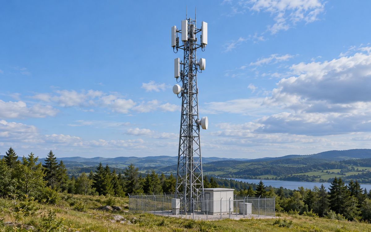
Illustrative application scene (AI-generated), not a project photograph.
1 Combination: tower form outdoors, ring form indoors
Combination: remote hilltop site = tower radial form; crowded indoor site = ring plus grading. An unattended hilltop tower is earthed like a transmission tower: a closed ring 3 m around the base, 10–20 m radials from the corners where the resistance exceeds 10 Ω, as few and as straight as possible, no rods and no backfill additives. A site in town, attended or sharing a building, follows building ring earthing with potential grading and whatever ground area is available, rather than chasing the cheapest radial.
Fundamentally telecom earthing is no different from power earthing: where grading matters (equipment rooms) lay more mesh, as in a substation; where lightning dominates (towers) lay more radials, as on a line tower. The industry's own code, YD 5098, made real progress on bonding and surge protection but is vague on how to bring impulse resistance down; what follows fills that in with power-earthing method.
2 Remote sites: ring plus radials
- Tower earth: weld the metalwork in the four footings together, run a closed ring 3 m around the base, welded reliably to the four base plates. YD 5098 asks for a mesh ≤ 3 × 3 m inside the tower footprint – useful for grading, almost useless for resistance (inner meshes shield each other), so do not expect a denser mesh to bring the resistance down.
- Radials: where the ring exceeds 10 Ω, run radials from the corners. Unless the resistivity is below about 120 Ω·m a 24 m ring cannot reach 10 Ω on its own, so nearly every hilltop site needs radials. Take the length from the tower radial design table within the effective length of GB 50169 Table 3.7.5; on slopes dig the trench along the contour and backfill with stones removed and compacted, or rain washes the electrode out.
- Three earths into one: the building ring, the tower earth and the transformer earth (within 40 m) joined by horizontal conductors into one closed grid of ≥ 1000 m²; below 700 Ω·m that area alone reaches 10 Ω.
- What not to do: rods ≥ 2.5 m (0.7 m in the trench leaves 1.8 m above ground, impossible to drive on a hilltop – in the power industry only substations have the conditions for them); brine or chemical backfill in the trench (short-lived, corrosive, long banned by utilities); "special earthing rods" (a rod's effect does not depend on its material, and driving rods in high-resistivity ground is the least effective measure there is).
3 Setting the target
YD 5098 says: below 700 Ω·m, site power-frequency resistance ≤ 10 Ω; above 700 Ω·m no limit, but an equivalent grid radius ≥ 20 m, 20–30 m radials at the corners, and upgraded first-stage SPDs and port protection as compensation.
Our advice is to follow the power industry – a permitted value graded by resistivity (GB/T 50065 Table 5.1.3: ≤ 100 Ω·m 10 Ω, 100–500 15 Ω, 500–1000 20 Ω, 1000–2000 25 Ω, > 2000 30 Ω) – and protect the equipment with SPDs and bonding. The reason is simple: utilities spend tens of thousands of yuan to bring a tower in high-resistivity ground to 20–30 Ω, while the telecom industry once demanded 5 Ω for two thousand yuan a site, and the result was faked measurements across the whole industry (section 6). Lower resistance does help against lightning – the same stroke gives a potential rise of the order of 1 000 V at 20 Ω and 10 000 V at 200 Ω, and an SPD absorbs no energy itself, it needs a sound earth to discharge into. But the target has to be achievable.
4 Site earth calculator
Power-frequency resistance of a base ring plus radials
GB/T 50065 Annex B horizontal-electrode formula on the total length (ring + radials); shape coefficient 0 for the ring alone, the tabulated value for the radial count once radials are added (ring and radials shield each other, so the result is 10–20 % optimistic). Example: 24 m ring + 4 × 10 m radials, ρ from 200 to 1000 Ω·m: R goes from about 7 Ω to 34 Ω (8 and 37 Ω allowing for mutual shielding) – the same drawing protects five times worse on one hill than another, which is why the target has to be graded.
5 Indoor and urban sites
Central offices, switching centres, data rooms and sites sharing a building have many people, dense equipment and little ground, so the approach shifts to building ring earthing (basic form ③):
- A ring around the building wall, bonded at many points to the foundation reinforcement, is the body of the earth; there is no room for radials in town and no need – urban resistivity is usually low and the building foundation alone gives a low enough resistance.
- Inside, an equipotential system (earthing bars, busbars, rack earths) in pure copper per DL/T 2650-2023 5.1.1.7; copper-clad steel replaces only the buried part.
- Grading rings around outdoor equipment people pass regularly (condensers, generators, transformers), designed for step and touch voltage rather than for the cheapest radial.
- Three to five rods clustered at the lightning down-lead speed up discharge – a grading measure that contributes almost nothing to overall resistance, not a resistance-reducing one.
6 Faked measurements: twelve hilltop sites
An operator built twelve hilltop sites with a ≤ 2 Ω requirement and a budget of 70 000 yuan per site. Contractor A took four, spent 40–50 000 per site, laid about 400 m of radials (a 60 m grading ring at the down-lead plus 4–6 radials) and passed acceptance; contractor B took eight, laid one radial of 80-odd metres with a dozen block electrodes hung on it per site, and also passed. Measured properly: every site sat on about 2000 Ω·m; A's four were all under 10 Ω, B's eight were all in the tens of ohms – and none reached 2 Ω, because 2 Ω on 2000 Ω·m costs at least 250 000 yuan before the effective-length limit of radials is even considered.
Both passed because the test leads were too short: an ordinary earth tester comes with a 40 m current lead and a 20 m potential lead, while the current electrode has to be 4–5 grid diagonals away for a true reading; short leads read far too low. We re-measured a mobile operator's lightning-damaged sites: the published values were all under 5 Ω, the true values all above 10 Ω and mostly above 20 Ω. So the industry statistic that "sites under 5 Ω suffer more lightning damage" does not show that low resistance is useless – it shows the data were false. At acceptance, insist on a current electrode ≥ 4 grid diagonals away, the potential electrode at 0.618, and lead lengths stated in the report.
7 Material and theft
Telecom sites are the worst hit by copper theft – unattended, remote, copper tape exposed at the tower feet. Copper-clad steel cannot be stripped and has negligible scrap value: the direct answer. Sizes: ring and radials Ø 10–12 annealed wire (bent along the contour on slopes), 0.6 mm copper (0.8 mm coastal and saline); exothermic welds at the tower feet; pure copper for indoor bars and busbars. 0.25 mm plated wire suits dry, low-corrosivity, maintainable lowland sites, not acidic hill ground (position 1).
8 What to send
Site type (hilltop / urban / shared building), soil resistivity (or site photos and a ground description), tower foundation type, positions and distances of building, tower and transformer, the operator's or tower company's earthing specification.
At a glance: typical selection
| Project type | Governing factor | Typical fault current / copper size | Soil and environment | Copper layer | Sizes (horizontal / vertical) | Replaceability |
|---|---|---|---|---|---|---|
| Telecom towers / base stations | Lightning, cost, speed | Small / 50 mm² | Any; dispersed sites | 0.25–0.6 | Ø10–12 ring / Ø14–16 rods (plated acceptable) | ★ Fully replaceable |
Have a project in mind?
Send the conductor size, length, soil and fault current – two sizing options and the copper saving come back within 24–48 hours, free.
Request the free assessmentJust a quotation